Having a mechanical system for the control panels is not enough - one also needs to be able to quickly connect and disconnect a panel to make it useful. Ideally you would like to be able to hot swap all panels without having to exit your front end.
I looked at several examples on the web of wiring schemes. Many people use Molex, RS-232 and even hard drive connectors to swap large panels. From my perspective these seemed too difficult to connect and disconnect.
One option considered was modular phone wires, but unfortunately the six wires were insufficient for wiring a 6 button panel (you need a ground). Someone on one forum suggested network cable (RJ45 or CAT 5 cable) wiring. Each connector has 8 wires, which is perfect for up to 7 buttons or a joystick plus three buttons, along with one input for ground. As I explored this further, the CAT5 looked more and more feasible.
The keystone wall jacks were another great idea from the web. In fact I used two of them in the final design. This allows very easy swapping of panels by just plugging and unplugging an RJ45 jack. The IPAC controller is mounted to the back side of the patch panel in the area between the wall outlets.
Two RJ45 Wall sockets provide plenty of connections for joysticks and buttons. A 4-port USB hub in the middle provides the analog connectivity needed for trackball, spinner & steering wheels. The IPAC-2 Controller sits on the back of the patch panel. The entire panel can be removed for servicing the IPAC by removing just two screws. | 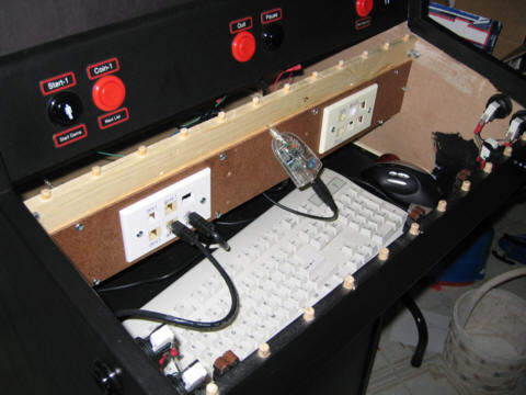 |
An obvious choice for analog controls was a USB hub. USB devices can be hot swapped on the fly, and with Analog MAME you can support multiple controls from a single hub. Once I figured out how to do a simple mouse hack (there are multiple sources on the web for this) it was a piece of cake to use a cheap USB mouse board to wire up the spinner and trackball. I had a four port USB hub laying around that cost less than $10, so I mounted it just under the control panel for easy swapping.
Two Six-Port RJ45 Keystone wall outlets were mounted to a panel below the control panel, one on the player 1 side and one on the player 2 side. A 2 player IPAC control interface board is mounted on the back of the panel and wired to the RJ45 jacks. Inputs were divided into JOY1, JOY2, BUTTON1, BUTTON2 and CONTROL inputs corresponding to the player 1 and 2 joysticks, buttons and various control button inputs.
Note that the CONTROL and pinball flipper buttons from the cabinet plug into RJ45 outlets as well. This allows you to unplug the RJ45 inputs and unscrew the entire panel holding the IPAC for maintenance or expansion later. There are no inputs wired directly to the IPAC - everthing goes through the RJ45 patch panel.
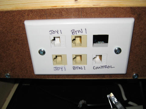
Below is a picture of the two wall outlets. Note that some inputs, such as player 1 joystick input are duplicated so you can have two joysticks mounted to the same input (for example a 4-way and an 8-way) for flexible use. All buttons from the cabinet (control and pinball buttons) also connect to RJ45 connectors and plug into this panel.
The Player 1 socket ended up with more inputs, primarily because I decided to wire the pinball buttons to the player 1 button inputs and also the control inputs happened to be on that side of the IPAC - making for shorter wires.
Player 1 Wall Socket | 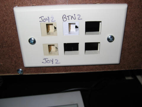 Player 2 Wall Socket |
The following ports were used - though some were duplicated in parallel:
Player 1 Side (6 port outlet):
| Player 2 Side: (6 port outlet):
|
Each RJ45 input has 8 wires, which is sufficient for 7 inputs plus a ground pin. Pin 1 was the ground pin in all cases to make them interchangeable. For example, you can plug a joystick into a button port or a button port into a joystick port if needed. This gives you the flexibility to play "dual tank" games by plugging player 1 joysticks into JOY1 and BTN1 and player 2 joysticks into JOY2 and BTN2 and then doing a lot of keyboard mapping.
The joystick inputs also have buttons 1 and 2 wired to them for button or trigger style joysticks. Button 7 on the joysticks is a special input that is wired to a separate button on many of my joystick panels that aligns with the normal six button panels to act as a "neo-geo" thumb button.
| Pin | Color | JOY | BUTTON | CONTROL |
| 1 | Stripe-Orange | ground | ground | ground |
| 2 | Orange | Up | BTN-1 | Start-1 |
| 3 | Stripe-Green | Down | BTN-2 | Start-2 |
| 4 | Blue | Left | BTN-3 | Coin-1 |
| 5 | Stripe-Blue | Right | BTN-4 | Coin-2 |
| 6 | Green | BTN-7 | BTN-5 | Pause |
| 7 | Stripe-Brown | BTN-1 | BTN-6 | Quit |
| 8 | Brown | BTN-2 | BTN-7 | Unused |
The panels themselves are wired up with RJ45 network cables cut in half. The patch cable is stapled to the board in several places so it can't be pulled out. The individual wires are either wired directly to a button or crimped with a 22 gauge wire which runs to the button.
Note that originally I used the extra 22 gauge wire because I had purchased only 3 foot network patch cables (which are too short to do all of the wiring directly), and also I saved most of the 22 gauge wiring from the original control panel. Later I decided this was a pretty good system because twisting the 22 gauge with the thin CAT5 cables results in a much better crimp connection than just crimping the very thin CAT5 cables. The 22 gauge wire also stands up much better to the frequent rough handling the panels get.
Close-up of the Q-bert diagonal mount joystick panel. The cable is a network patch cable cut in half. Staples hold the main cable in place. Crimp connectors "splice" the network cable to more robust 22 gauge wire. | 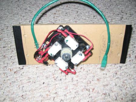 |
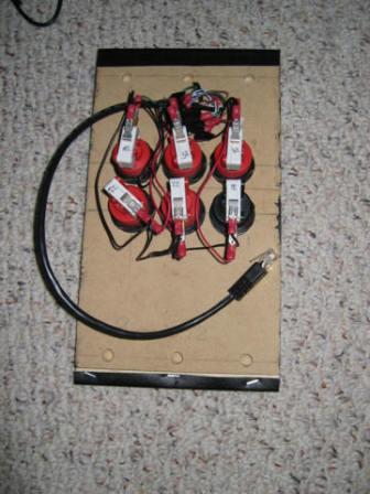 | A six button panel. While not too pretty, you can see that the CAT5 patch cable comes to the board and then is spliced into some 22 gauge wiring with standard terminals. The buttons and joysticks were already wired from the original panel, so I used this splicing method to preserve much of the original wiring. It has been robust so far despite the frequent handling the panels get. |
The IPAC side of things is substantially simplified by the use of "Keystone" jacks. The wiring was done with CAT5 Cable cut from the middle of a longer patch cable. CAT5 cable is simply inserted into each keystone jack, much as you would with a normal network wall outlet. The other end of the wires is screwed down on the IPAC terminal much as you would any wire.
The only complexity comes from the large number of duplicate inputs. For example, both the JOY1 and JOY2 inputs were duplicated in full in parallel, which required twisting inputs together and connecting them under the IPAC terminal. Some inputs such as BTN-1 had to be split multiple times to appear both on duplicate button terminals and as an input to the joystick panels. In these cases, I frequently crimped several inputs together at an intermediate point separate from the IPAC terminal.
The RJ45 wires are very thin and not easy to crimp on their own. They can also be broken if mishandled. Some precautions are needed.
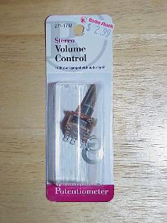
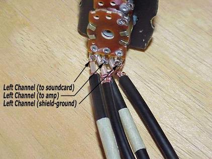
I originally tried dissecting my stereo sound system to see if there was an easy way to implement a volume control. It turned out to be quite difficult because there were a lot of surface mount parts. Later I found a link on Oscar's site that provided an easy way to mount a volume control on the cabinet. It involves the very simple method of using a Radio Shack Stereo Pot (item #271-1732 - 100K Ohm Stereo Control) on the wires connecting the computer to your stereo. This system also has the advantage that it works with any stereo system. You must wire it on the wiring between the computer and stereo system, NOT on the output of the stereo system since the pot will not tolerate the power on the output side of the stereo. You can mount the pot anywhere on your case and add a knob to it for instant access to the volume. Mine is mounted right on the front of the cabinet just below the controls.
Some pictures - taken by Oscar - visit his site for more details.
Oscar's Volume Control - A simple/cheap way to add a volume control
I wired two separate power switches to my computer, as well as a power-up button. Two high voltage switches from Radio shack are wired into two power strips for the main system. The master power button controls all power coming into the cabinet, and can be used when completely shutting down the system. A second power switch controls just the marquee light, monitor and sound system. This way I can power down the monitor, sound and lights when the system is not in use, but keep the main computer running.
A momentary switch is wired into the "power on" chassis connector for the personal computer. This is equivalent to pressing the "power on" button on the computer. Therefore to power on the system, all you need to do is turn the power switch on and press the momentary button. This will boot the computer completely. When you are done playing, just return to the main menu and press the momentary button again and the computer will do a proper shutdown.